|
|
|
Who's Online
There currently are 5960 guests online. |
|
Categories
|
|
Information
|
|
Featured Product
|
|
|
 |
|
|
There are currently no product reviews.
 ;
Very fast and perfect delivery. Clear and well scanned. A lot of work professionally realized.
Again thak you a lot
 ;
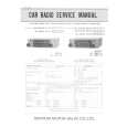
This manual is accurate and of high quality. It is only volume 2 of the service manual. This is schematic, parts lists, and exploded mechanical drawings. The theory of operation and the diss-assembly instructions are in volume 1. The unit can be tricky to dis-assemble portions of so the volume 1 manual can be important. The product description of the manual is accurate but it does not say anything about volume 1 and the image of the front page does clearly say Volume 2.
;
Wellll again thank you very much fast and effective. Clear and well done for such an old TV!!!!
;
It has all the information you will need to fix it. The main circuit diagram is only A4 but being a PDF, you can print it to any size - I did it on two sheets of A3 and it didnt lose any detail - just made it readable when pinned up above the bench. I've found the fault, just need to buy some obscure bits to get it going again!
I cant fault the process, I paid for the manual in the morning and it was ready to download by lunch time.
;
Very good copy in a 54 pages PDF archive. This is my sixth purchase here. :)
3. The base and handset cannot be connected.
Check whether the base NG is able to set in the test mode 1. OK Check the TX POWER NG and the TX FREQUENCY on the base unit. OK Press PAGE key twice, NG check whether deviation of the TX data is app. 8 kHz Dev. OK Check D8, IC1 and their peripheral circuits. Check whether there is a NG 250 Hz data waveform at C168. OK Check RT2, R98, R122, R123, R125, R126, C92 and C147. Check RT1, Q4, IC1 and their peripheral circuits. Check IC6 and its peripheral circuit.
Press PAGE key 7 NG times, 902.952467 MHz (250 Hz ±8 kHz Dev.) 1mV output signal from RF jack is applied. Can the IN USE LED be lighted? OK
Check whether there is a NG 250 Hz data waveform at Pin 9 of IC4. OK
Check IC1, FT2 and the peripheral circuit of IC4.
Check whether there is a NG 250 Hz data waveform at Pin 3 of IC2. OK Check whether there is a NG 250 Hz data waveform at Pin 34 of IC6. OK Check IC6 and its peripheral circuit.
Check RT4 and its peripheral circuit.
Check R78, R79, IC2 and their peripheral circuits.
Check whether the NG handset is able to set in the test mode 1. OK Check the TX POWER NG and the TX FREQUENCY on the handset unit. OK A
Check IC608 and its peripheral circuit.
Check RT601, Q602, IC601 and their peripheral circuits.
� 15 �
|
|
|
> |
|