|
|
|
Who's Online
There currently are 5701 guests online. |
|
Categories
|
|
Information
|
|
Featured Product
|
|
|
 |
|
|
There are currently no product reviews.
 ;
Very fast and perfect delivery. Clear and well scanned. A lot of work professionally realized.
Again thak you a lot
 ;
This manual is accurate and of high quality. It is only volume 2 of the service manual. This is schematic, parts lists, and exploded mechanical drawings. The theory of operation and the diss-assembly instructions are in volume 1. The unit can be tricky to dis-assemble portions of so the volume 1 manual can be important. The product description of the manual is accurate but it does not say anything about volume 1 and the image of the front page does clearly say Volume 2.
;
Wellll again thank you very much fast and effective. Clear and well done for such an old TV!!!!
;
It has all the information you will need to fix it. The main circuit diagram is only A4 but being a PDF, you can print it to any size - I did it on two sheets of A3 and it didnt lose any detail - just made it readable when pinned up above the bench. I've found the fault, just need to buy some obscure bits to get it going again!
I cant fault the process, I paid for the manual in the morning and it was ready to download by lunch time.
;
Very good copy in a 54 pages PDF archive. This is my sixth purchase here. :)
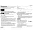
DISASSEMBLY INSTRUCTIONS
1-6: DVD DECK (Refer to Fig. 1-6) 1. Make the short circuit on the position as shown Fig. 1-6 using a soldering. If you remove the DVD Deck with no soldering, the Laser may be damaged. 2. Disconnect the following connectors: (CP2601, CP2602, CP2603). 3. Remove the 4 screws 1. 4. Remove the DVD Deck in the direction of arrow.
1 1 1 11 11 1
Make the short circuit using a soldering. Pick Up PCB
1-8: AV PCB/RELAY PCB (Refer to Fig. 1-8) 1. Remove the 6 screws 1. 2. Remove the 2 screws 2. 3. Remove the AV PCB and Relay PCB in the direction of arrow.
2
Relay PCB
AV PCB
2
DVD Deck
1
1
Fig. 1-8
Fig. 1-6 1-7: DVD PCB (Refer to Fig. 1-7) 1. Disconnect the following connectors: (CP2001 and CP8002). 2. Remove the 4 screws 1. 3. Remove the 3 screws 2. 4. Remove the screw 3. 5. Remove the DVD PCB in the direction of arrow.
1 1 1 1
DVD PCB
3 22 2
Fig. 1-7
B1-2
|
|
|
> |
|