|
|
|
Who's Online
There currently are 6037 guests online. |
|
Categories
|
|
Information
|
|
Featured Product
|
|
|
 |
|
|
There are currently no product reviews.
 ;
It was very usefull, it is clear the quality is super, the price I paid is very afordable.
Generally speaking Iam very happy with this company.
;
The manual was exactly what I needed, Good quality scans too. superb.
;
I am so happy found this site as it consists of so many Manuls and easy to aquire. This onei s exactly what I wanted and much more as it has info on not only how to use the tuner but how to repair it as well. I will come here 1st before purchasing else where! Thanks owner-manual.com!
;
Top class product, I printed it out on A3 paper and it is clear and very easy to follow.
Cheaper than buying a new radio!
;
is part of the manual is very useful for repairing
Here are circuit diagrams
if there is damage, I recommend using this part of the
a complete list of circuit boards and components
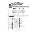
TOSHIBA V 856 B
Mechanical Adjustments Cont�d
Note: � For the cam slider mounting, refer to the notes in item 1-6-41. d) Confirm that the clearance between the drive lever and the cam gear is approx. 2 mm. (Confirm that the drive lever is correctly mounted on the groove of the cam gear.) e) Confirm that the v mark on the rotor of the cam switch aligns with the A mark on the motor bracket. 5. After completion above steps a) to e), mount the loading drive assembly. Push four claws to the motor bracket in the order of (d) > (c) > (b) > (a) and push the portion (A) (No. 8 guide cap) into the motor bracket. 6. Confirm that the v mark on the rotor of the cam switch aligns with that on the bracket when the hole b) on the cam gear aligns with the hole on the mechanical deck. If the alignment of the A marks cannot be confirmed, remove loading drive assembly once again and reinstall after confirming the above steps a) to e). 7. Mount two flat cables. 8. Mount the F/L ground plate and the head cleaner assembly.
6
6. Replace the loading drive unit (7). When mounting the PC boards of the cam switch (5) and the loading drive unit (7), take care that no clearance is allowed. 7. Insert the loading drive unit (7) and the worm gear (4) into the loading drive bracket (3). 8. Push the tip (G) of the worm gear (4) into the claw (B) on the loading motor bracket. In this process, take care not to bend the tip of the worm gear with strong pressure. 9. Push the cam switch (5) into the claw (F) on the loading motor bracket. 10.Mount the parts in the reverse order of removal. 7. Make the S. T slider to the slot out condition. 8. Push the cam lever (1) and the pin (2) (loading slider) in the direction shown by the arrows (A) and (B). 9. Mount the cam gear at the angle which the small hole (a) on the cam gear aligns with the hole on the mechanical deck. (Refer to Fig. 631-1.) 1-6-33. T Reel Table Assembly and Washer 2 Replacement 1. Remove the top bracket and the cassette holder assembly. (Refer to item �1-6-1. Top Bracket Replacement and 1-6-2. Cassette Holder Assembly Replacement�.) 2. Remove the drive arm assembly. (Refer to item �1-6-5. Drive Arm Assembly Replacement�.) 3. Remove the T soft brake and T main brake assembly (Refer to item �l-6-41. Cam Slider Replacement�.) 4. Remove the T reel table assembly (1) pulling it out upward. 5. Remove the washer 2 (2). 6. After cleaning the reel shaft (3) with a cleaning kit, insert a new washer 2 (2) to the reel shaft (3) and apply a drop of oil to the shaded portions (two locations) on the reel shaft (3). 7. After replacing, mount the parts in the reverse order of removal. 8. Confirm the reel torque using a torque cassette.
www.u-view.co.uk
Fig. 6-28-1 1-6-29. Loading Drive Assembly Replacement 1. Remove the F/L ground plate and the head cleaner assembly. (Refer to item �1-6-14. Head Cleaner Assembly Replacement�.) 2. Remove two flat cables (1) from the connectors. 3. Pull out the portion (A) (No. 8 guide cap) from the motor bracket (2). 4. Remove four claws (a), (b), (c), (d) securing the motor bracket in the order of (a) > (b) > (c) > (d).
Fig. 6-31-2 10.Mount the parts in the reverse order of removal. 1-6-32. S Reel Table Assembly and Washer 2 Replacement 1. Remove the top bracket and the cassette holder assembly. (Refer to item �1-6-1. Top Bracket Replacement and �1-6-2. Cassette Holder Assembly Replacement�.) 2. Remove the drive arm assembly. (Refer to item �1-6-5. Drive Arm Assembly Replacement�.) 3. Remove the cam slider. (Refer to item �1-641. Cam Slider Replacement�.) 4. Remove the S soft brake and S main brake assembly. (Refer to item �1-6-38. S Soft Brake Replacement and 1-6-37. S Main Brake Assembly Replacement�.) 5. Remove the tension lever assembly. (Refer to item �1-6-23. Tension Lever Assembly Replacement�.) 6. Remove the S reel table assembly (1) pulling it out upward. 7. Remove the washer 2 (2). 8. After cleaning the reel shaft (3) with a cleaning kit, insert a new washer 2 (2) to the reel shaft (3) and apply a drop of oil to the shaded portions (two locations) on the reel shaft (3). 9. After replacing, mount the parts in the reverse order of removal. 10.Confirm the reel torque using a torque cassette. Note: � The washer 2 (2) can use repeatedly. Fig. 6-34-1
Fig. 6-33-1 Note: � Washer 2 (2) can use repeatedly. 1-6-34. Idle Arm Assembly Replacement (Center Gear Pulley, Idle Kick Lever Idle up/ down Lever) 1. Remove the mechanical deck from the main PC board. 2. Remove the stop ring (1) turning over the mechanical deck. 3. Remove the center gear pulley (2) lifting it upward. 4. Remove the claw (A) on the idle kick lever (3) moving and pulling it upward. 5. Remove the slit washer (4). 6. Remove the idle up/down lever (5) and the idle arm (6) simultaneously from two claws (B) on the mechanical deck. 7. After cleaning the center gear post (7) using a cleaning kit, apply a few drops of oil to the shaded portion on the center gear post. 8. Mount the parts in the reverse order of removal. Note: � Stop ring (1) is impossible to use again. � When mounting the parts, take care of the notice shown in Fig. 6-34-2.
Fig. 6-34-2 1-6-35. Holder Center Post Assembly Replacement 1. Turn over the mechanical deck and remove the center gear pulley and the idle arm. (Refer to item �1-6-34. Idle Arm Assembly Replacement�.) 2. Turn over the mechanical deck and remove the top bracket and the cassette holder assembly. (Refer to item �1-6-1. Top Bracket Assembly Replacement and 1-6-2. Cassette Holder Assembly Replacement�.) 3. Remove the drive arm assembly. (Refer to item �1-6-5. Drive Arm Assembly Replacement�.) 4. After removing two screws (1), replace the holder center post assembly (2). 5. After replacing, mount the parts in the reverse order of removal.
Fig. 6-29-1 Note: � Remove the claw (a) inserting a driver. � Remove the claws (b) and (c) pushing inside previously and opening the claws slightly. Fig. 6-29-3 1-6-30. Loading Motor Sub Assembly, Cam Switch and Loading Drive Unit Replacement 1. Remove the loading drive assembly. (Refer to item �1-6-29. Loading Drive Assembly Replacement�.) 2. Remove the cleaner assist lever (1) from the claw (A). 3. After removing the cleaner assist lever (1), the worm wheel can be also removed upward. 4. Insert a slot-type screwdriver into the portion (C) of the loading drive bracket (3) and push the loading motor 2 - 3 mm lower. And push the tip of worm gear from the portion (D) of the loading bracket (3), then remove the worm gear (4) from the claw (E). 5. Remove the cam switch (5) from the claw (F) on the loading drive bracket (3) and pull out the loading drive unit (7) and the worm gear (4) simultaneously.
Fig. 6-30-1 1-6-31.Cam Gear Replacement 1. Remove the loading drive assembly. (Refer to item �1-6-29. Loading Drive Assembly Replacement�.) 2. Remove the cam slider. (Refer to item �1-641. Cam Slider Replacement�.) 3. Remove the drive lever. (Refer to item �1-640. Drive Lever Replacement�.) 4. Remove the pinch roller assembly. (Refer to item �1-6-21. Pinch Assembly Replacement�.) 5. Remove the cam gear. 6. Apply grease on a new cam gear on the shaded portion as shown in Fig. 6-31-1 and the shaft of the main base.
Fig. 6-29-2 <Preparation for Loading drive assembly mounting> a) Confirm that the head cleaner assembly is removed. b) Confirm that the small hole b) on the cam gear aligns with the hole on the mechanical deck. c) Confirm that the clearance between the pinch lever assembly and the cam gear is approx. 0.3 mm. (Confirm that the pinch lever assembly is correctly mounted on the groove of the cam gear.)
Fig. 6-31-1
Fig. 6-32-1
Fig. 6-35-1
|
|
|
> |
|