|
|
|
Who's Online
There currently are 5818 guests online. |
|
Categories
|
|
Information
|
|
Featured Product
|
|
|
 |
|
|
There are currently no product reviews.
 ;
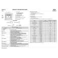
This is a good quality scan of the Operation & Maintenance (Service) Manual for the PAL version of this high-band broadcast umatic, BVU-800P
All schematics and lineup procedures appear to be included in this one manual AFAICT.
The file size is just over 113 MB which gives an idea of the quality and number of pages.
All of the schematics, which contain some fairly small print, are easily readable when you zoom into the page.
John Thompson, Newcastle Upon Tyne, England.
;
Good quality, all schematics of few of models. There is also short form of user manual and regulation manual.
;
Perfect copy of the service manual. you can enlarge every page, and it comes up
with all details.
;
It´s very very nice manual with all, what i need. Original in good quality. Very fast business. Very much thanks...
;
Purchased the manual that I was looking for at a great price and could download it easily.. Great service experience and for future purchases I plan to use the site.
Thank you very much
ELECTRICAL ADJUSTMENTS
2-4: FOCUS 1. Receive a broadcast. 2. Turn the Focus Volume fully counterclockwise once. 3. Adjust the Focus Volume until picture is distinct. 2-5: HORIZONTAL POSITION 1. Receive the monoscope pattern from the Pattern Generator. 2. Using the remote control, set the brightness and contrast to normal position. 3. Activate the adjustment mode display of Fig. 1-1 and press the channel button (08) on the remote control to select "H POSI 50". 4. Press the LEFT/RIGHT button on the remote control until the SHIFT quantity of the OVER SCAN on right and left becomes minimum. 5. Receive the cross hatch signal of NTSC. (Audio Video Input) 6. Press the AV button on the remote control to set to the AV mode. 7. Activate the adjustment mode display of Fig. 1-1 and press the channel button (39) on the remote control to select "H POSI 60". 8. Press the LEFT/RIGHT button on the remote control until the SHIFT quantity of the OVER SCAN on right and left becomes minimum. 2-6: VERTICAL POSITION NOTE: Adjust after performing adjustments in section 2-5. 1. Receive the monoscope pattern from the Pattern Generator. 2. Using the remote control, set the brightness and contrast to normal position. 3. Activate the adjustment mode display of Fig. 1-1 and press the channel button (09) on the remote control to select "V POSI (50)". 4. Check if the step No. V. POSI (50) is "10". 5. Adjust the VR402 until the horizontal line becomes fit to the notch of the shadow mask. 6. Receive the cross hatch signal of NTSC. (Audio Video Input) 7. Press the AV button on the remote control to set to the AV mode. 8. Using the remote control, set the brightness and contrast to normal position. 9. Activate the adjustment mode display of Fig. 1-1 and press the channel button (10) on the remote control to select "V POSI (60)". 10. Check if the step No. V. POSI (60) is "00". 2-7: VERTICAL SIZE NOTE: Adjust after performing adjustments in section 2-6. 1. Receive the monoscope pattern from the Pattern Generator. 2. Using the remote control, set the brightness and contrast to normal position. 3. Activate the adjustment mode display of Fig. 1-1 and press the channel button (11) on the remote control to select "V SIZE 50". 4. Adjust by using the LEFT/RIGHT button on the remote control so that the Up/Down OVER SCAN Quantity becomes equal to the Right/Left OVER SCAN Quantity. 5. Receive a broadcast and check if the picture is normal. 6. Receive the cross hatch signal of NTSC. (Audio Video Input) 7. Press the AV button on the remote control to set to the AV mode. 8. Activate the adjustment mode display of Fig. 1-1 and press the channel button (12) on the remote control to select "V SIZE 60". 9. Adjust by using the LEFT/RIGHT button on the remote control so that the Up/Down OVER SCAN Quantity becomes equal to the Right/Left OVER SCAN Quantity. 10. Receive a broadcast and check if the picture is normal. 2-8: VERTICAL LINEARITY NOTE: Adjust after performing adjustments in section 2-7. After the adjustment of Vertical Linearity, reconfirm the Vertical Position and Vertical Size adjustments. 1. Receive the monoscope pattern from the Pattern Generator. 2. Using the remote control, set the brightness and contrast to normal position. 3. Adjust the VR401 until the SHIFT quantity of the OVER SCAN on upside and downside becomes minimum. 2-9: OSD HORIZONTAL 1. Using the remote control, set the brightness and contrast to normal position. 2. Activate the adjustment mode display of Fig. 1-1 and press the channel button (35) on the remote control to select "H POSI OSD". 3. Press the LEFT/RIGHT button on the remote control until the difference of A and B becomes minimum. (Refer to Fig. 2-1)
35 36 37 38 39 00
H POSI OSD V POSI OSD H POSI TEXT V POSI TEXT H POSI 60 CUT OFF 9- EXT
129 57 125 57 42
VCO Status XXX
-
A
B Fig. 2-1
D-2
|
|
|
> |
|