|
|
|
Who's Online
There currently are 5748 guests online. |
|
Categories
|
|
Information
|
|
Featured Product
|
|
|
 |
|
|
There are currently no product reviews.
 ;
The content of the manual was not found on the Internet and was a hard find. I check the net for 5 hours until I came across this web-site. When I did find the book it Auto loaded into my IPAD PDF shelf for books for review at anytime. Overall I am satisfied with the book and it answered all my questions. This repair book is obsolete because the product I bout it for is pretty old. Thanks for the help with the download and even having the manual. Thanks 73's K5HRD
;
Excellent manual including schematics. The service was great and the manual helped complete the job.
;
It was magic after so many years to still be able to source this info. It was equally amazing to return my Pioneer receiver to it near new sound quality AFTER NEARLY 30 YEARS! Thank you for this ability!
;
Very quick and easy website to use and fast download of manual, quality of manual is excellent and will be pleased to use this service again in the future, thanks so much!
 ;
Easy and secure way to get a complete service manual of a vintage hifi component. Only some parts of the print copy are dificult to read. Nice price!
ELECTRICAL ADJUSTMENTS
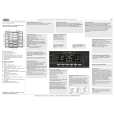
2-10: VERTICAL LINEARITY NOTE: Adjust after performing adjustments in section 2-9. 1. Receive the cross hatch signal from the Pattern Generator. 2. Using the remote control, set the brightness and contrast to normal position. 3. Activate the adjustment mode display of Fig. 1-1 and press the channel button (1) on the remote control to select "H/V". The Fig. 2-4 appears on the display. 4. Press the channel button (5) on the remote control to select "V. LIN 50/60". 5. Press the PLAY or STOP button on the remote control until the SHIFT quantity of the OVER SCAN on upside and downside becomes minimum. 6. Receive the cross hatch signal of NTSC. (Audio Video Input) 7. Press the AV button on the remote control to set to the AV mode. Then perform the above adjustments 2~5. 2-11: VERTICAL POSITION NOTE: Adjust after performing adjustments in section 2-10. 1. Receive the center cross signal from the Pattern Generator. 2. Using the remote control, set the brightness and contrast to normal position. 3. Activate the adjustment mode display of Fig. 1-1 and press the channel button (1) on the remote control to select "H/V". The Fig. 2-4 appears on the display. 4. Press the channel button (4) on the remote control to select "V. POSI 50/60". 5. Press the PLAY or STOP button on the remote control until the horizontal line becomes fit to the notch of the shadow mask. 6. Receive the center cross signal of NTSC. (Audio Video Input) 7. Press the AV button on the remote control to set to the AV mode. Then perform the above adjustments 2~5. 2-12: OSD HORIZONTAL 1. Using the remote control, set the brightness and contrast to normal position. 2. Activate the adjustment mode display of Fig. 1-1 and press the channel button (5) on the remote control to select "OTHERS". The Fig. 2-2 appears on the display. 3. Press the channel button (4) on the remote control to select "OSD H". 4. Press the PLAY or STOP button on the remote control until the difference of A and B becomes minimum. (Refer to Fig. 2-5) 2-13: SUB BRIGHTNESS 1. Receive the monoscope pattern (80dB). (RF Input) 2. Using the remote control, set the brightness to minimum position and contrast to maximum position. 3. Activate the adjustment mode display of Fig. 1-1 and press the channel button (4) on the remote control to select "PICTURE". The Fig. 2-6 appears on the display. 4. Press the channel button (1) on the remote control to select "BRIGHT". 5. Press the PLAY or STOP button on the remote control until the white 25% is starting to be visible. 6. Receive the monoscope pattern. (Audio Video Input) 7. Press the AV button on the remote control to set to the AV mode. Then perform the above adjustments 2~5. 1. BRIGHT 2. CONTRAST 3. COLOUR 4. TINT 5. SHARPNESS 6. OSD CONT 7. 8.
0. RETURN
Fig. 2-6 2-14: SUB COLOR 1. Receive the color bar pattern. (RF Input) 2. Using the remote control, set the brightness, contrast and color to normal position. 3. Connect the synchro scope to TP801. 4. Activate the adjustment mode display of Fig. 1-1 and press the channel button (4) on the remote control to select "PICTURE". The Fig. 2-6 appears on the display. 5. Press the channel button (3) on the remote control to select "COLOR". 6. Adjust the VOLTS RANGE VARIABLE knob of the oscilloscope until the range between white 100% and 0% is set to 4 scales on the screen of the oscilloscope. 7. Press the PLAY or STOP button on the remote control until the red color level is adjusted to 95% of the white level. (Refer to Fig. 2-7) 8. Receive the color bar pattern. (Audio Video Input) 9. Press the AV button on the remote control to set to the AV mode. Then perform the above adjustments 2~7. White 0%
0% [ TV ] 95%
OSD H
Red Level White 100% Fig. 2-7
A
B
Fig. 2-5
|
|
|
> |
|